Key Fob Remote Controlled Switch 4-Channel General Purpose Long Range Wireless
Highlights
- 4-Channel General Purpose 5 or 10-Amp SPDT Relays
- Key Fob Remote Controlled Relays with Antenna
- 750 to 1,000 Foot Range Depending on Remote
- Pair up to 40 Key Fob Remotes with Security Encryption
- Wireless Remote Relay Control with Programmable Functions
- Programmable Relay Functions Including:
- Relay Flash, Toggle, On/Off, and Timer Control
- Configure with your PC over USB then Install Permanently
- 12VDC Operation with Relay and Busy/Ready LEDs
Long-Range Remote Controlled Switch 4-Channel with General Purpose SPDT Relays
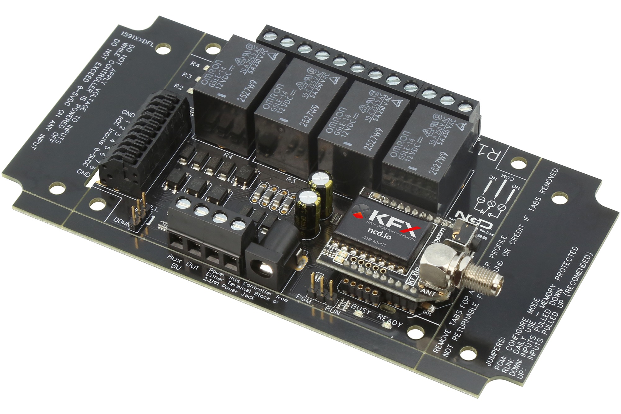
This 4-Channel general purpose relay board is controlled from a programmable remote control Key Fob. Available with 5 or 10-Amp SPDT relays (configured during purchase). Built on ProXR, our Key Fob controllers are capable of controlling relays in a wide variety of ways. Configure Key Fob buttons to toggle a relay, turn a relay on or off, Flash a relay, activate a relay for a period of time, and more. The KFX series Key Fob controllers are unique in the industry because they provide tremendous relay control functionality. This controller is equipped with general purpose relays, ideal for small motors, lights, and other automation applications. KFX series controllers are available with an industry leading 750 or 1,000 foot range remote controls, configured during purchase. Configure the KFX Key Fob receiver with your computer. Once configured, a computer is no-longer required. We can also custom pre-configure Key Fob controllers for you so they are ready for installation upon receipt. Pair up to 40 remotes with a single Key Fob relay controller with complete security encryption. Every remote will control the relays in the same way. Operates on 12VDC. Power supply, Key Fob remote controls, and other accessories sold separately.
About Key Fob Relays
Our 2nd generation Key Fob Series controllers allow users to control relays from a hand-held remote up to 750 feet away! Configure buttons to toggle relays, turn relays on and off, activate timers and control relay flashers. Integrated security features prevent unauthorized operation while maintaining easy configuration. Pair up to 40 different Key Fob remotes to a single controller.
How it Works
The Key Fob series controllers include a custom designed KFX Receiver to receive Key Fob signals and send pre-programmed data to the relay controller. When a button is pressed on the Key Fob, the KFX Receiver will send up to 9 bytes of data to the relay controller.
The KFX Receiver can be removed from the relay controller and connected to a computer for easy configuration. The KFX Receiver can be configured for button press and button release events. Use our free Base Station software to change the settings inside the KFX Receiver for controlling relays in different ways, such as relay timers, toggle commands, relay on/off and relay flashers.
The KFX Receiver can be configured for button press and button release events. If you intend to use smaller key fobs with less than 8 buttons, it is possible to use the extra KFX memory to send more than 9 bytes when buttons are pressed and released.
Additional Information
With a single KFX receiver module, users may associate up to 40 key fobs, including 1, 2, 3, 4, 5 and 8-Button remotes. KFX modules reach working distances of up to 750 feet, with superior responsiveness over previous generations of Key Fob receivers. Every Key Fob paired with a KFX Receiver will perform the exact same function as another Key Fob paired with the same KFX Receiver. It is not possible for each remote to be separately identified and generate different data. Put simply, every remote does exactly the same thing when paired with the same KFX Receiver.
Key Fob Configuration
The KFX Receiver Module is configured using our Base Station Software, and must be plugged into the ZIGMO only during configuration. Only one ZIGMO is needed regardless of the number of KFX Receivers you intend to use. The ZIGMO acts as an interface between your computer and the KFX Receiver, allowing you to define the Baud Rate, and Data Bytes that are transmitted for each Key Fob button Press. The ZIGMO is included with the KFX Integration Kit.
Note: We do advise that if you are pairing numerous key fobs to a given KFX receiver module that the button number on each Key Fob is the same for all key fobs, however, this is not absolutely required, but it may make using the KFX easier.
Associated Part Numbers
This product may have been previously manufactured using a part number shown below:
Relay Options

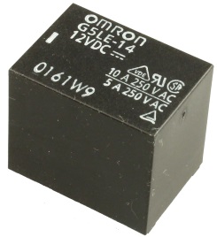
10-Amp SPDT Signal Relay Option
This controller is available with a 10-Amp relay option, allowing control of higher-power loads up to an absolute maximum of 240VAC at 10 Amps. Ideal for general purpose switching applications, this relays is focused on power-switching, and should never be used for low-power signals due to a higher On resistance of up to 150 Ohms when relay contacts are new (contact resistance drops to less than 1 Ohm after break-in period). The 10-Amp relay is of the SPDT variety, which provides Common (C), Normally Open (NO), and Normally Closed (NC) connections. Common is connected to NC when the relay is off. Common disconnects from NC and connects to NO when the relay is activated. All connections are made via screw terminals, capable of accepting up to 12 AWG wire. Review Datasheet

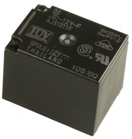
5-Amp SPDT Signal Relay Option
This controller is available with a 5-Amp relay option, allowing control of higher-power loads up to an absolute maximum of 240VAC at 5 Amps. Ideal for general purpose switching applications, this relays is focused on power-switching, and should never be used for low-power signals due to a higher On resistance of up to 150 Ohms when relay contacts are new (contact resistance drops to less than 1 Ohm after break-in period). The 5-Amp relay is of the SPDT variety, which provides Common (C), Normally Open (NO), and Normally Closed (NC) connections. Common is connected to NC when the relay is off. Common disconnects from NC and connects to NO when the relay is activated. All connections are made via screw terminals, capable of accepting up to 12 AWG wire. Review Datasheet
Mechanical Drawing
Wiring Diagrams
Essential
Communications
Tutorials
- Controlling Inductive Devices: Managing Induction & Electromagnetic Interference
- Introduction to Computer Controlled Relays and Switching
- Relay Logic
Download NCD Base Station
Official Repository
Introduction to Relay Control
This video will guide you in determining which relay controller you need for your application as well as a general overview of the differences between Relay Options. If you’re new to our products or just need a refresher for a new application this is a great place to start.
Induction Suppression
Learn about Induction and how it comes into play with Relay Controllers. Induction suppression can make your Relay Control applications intermittent and unreliable. This video will show you what causes it, how to avoid it, and how to account for it in your application.
SPDT Relay Controller Specifications
This table covers all NCD SPDT Relay Controllers. All ratings assume 12VDC operation at 70°F (21°C). Please note that most ratings are estimated and may be subject to periodic revision. Some ratings represent stock controller settings without performance enhancement optimizations. The estimated processing time can be impacted by background services and choice of commands. Standby power consumption assume no communications module is installed and no relays are active on the controller. Please add the power consumption of the activated relays and communications module to obtain a better estimation of power consumption.| Specifications of NCD SPDT Relay Controllers | Minimum | Nominal | Maximum | Notes |
|---|---|---|---|---|
| Operational Voltages | 10VDC | 12VDC | 15VDC | |
| Standby Power Consumption | 35mA | 100mA | 200mA | No Active Relays, No Com Module |
| Relay Power Consumption | 28mA | 35mA | 60mA | Consumption of Each Activated Relay |
| Operational Temperature Range | -40°F (-40°C) | 70°F (21°C) | 185°F (85°C) | Theoretical Component Limits Shown |
| Storage Temperature Range | -67°F (-55°C) | 70°F (21°C) | 185°F (85°C) | Theoretical Component Limits Shown |
| Operational Ambient Air Humidity | 0% | 50% | 70% | Non-Condensing Humidity Values Shown |
| Relay Activation Time | 4ms | 5ms | 10ms | Needs Further Validation |
| Relay Deactivation Time | 5mS | 10mS | 15mS | Needs Further Validation |
Communication Module Specifications
This table covers all NCD Communication Modules. While NCD communication modules operate at 3.3VDC, the ratings below highlight the effect they will have on the master controller operating at 12VDC at 70°F (21°C). Maximum ratings should be used for power budget planning purposes and may reflect short term absolute maximum peak current consumption. Some ratings are estimated and subject to periodic revision.| Specifications of NCD Communication Modules | Minimum | Nominal | Maximum | Notes |
|---|---|---|---|---|
| Operational Temperature Range | -40°F (-40°C) | 70°F (21°C) | 185°F (85°C) | Theoretical Component Limits Shown |
| Storage Temperature Range | -67°F (-55°C) | 70°F (21°C) | 185°F (85°C) | Theoretical Component Limits Shown |
| Operational Ambient Air Humidity | 0% | 50% | 70% | Non-Condensing Humidity Values Shown |
| USB Communications Module Power Consumption | NA | NA | NA | USB Modules are Powered by the USB Port Do Not Consume Device Current |
| RS-232 Communications Module Power Consumption | 10mA | 20mA | ||
| RS-485 Communications Module Power Consumption | 20mA | 35mA | ||
| Ethernet Communications Module Power Consumption | 58mA | 82mA | 100mA | |
| WiFi Bluetooth USB Communications Module Power Consumption | 37mA | 50mA | 100mA | Up to 300 Foot Indoor Wireless Range, Unobstructed. Up to 50 Foot Range Through Walls. |
| 900MHz Wireless Communications Module Power Consumption | 13mA | 30mA | 50mA | Up to 1,000 Foot Indoor Wireless Range, up to 2 Mile Outdoor Wireless Range using Included Antennas. Up to 28 Miles Outdoor Wireless Range using High-Gain Antennas. |
| 868MHz Wireless Communications Module Power Consumption | 17mA | 30mA | 50mA | |
| 2.4GHz Wireless Communications Module Power Consumption | 8mA | 20mA | 30mA | |
| KFX Wireless Key Fob Communications Module Power Consumption | 11mA | 15mA | 25mA | Up to 200 Feet Outdoor Wireless Range using 1, 2, 3, 4, or 5 Button Key Fobs. Up to 700 Feet Outdoor Wireless Range using 8-Button Remotes. |
AD8 Analog Input Usage Notice
Analog Inputs should not have a voltage present when powered down. Use a 220 Ohm current limiting resistor on each input to prevent damage to the controller if voltage will be present on the analog input when this controller is powered down. Do not exceed 0 to 5VDC on any analog input or the on-board CPU will be damaged. Most analog inputs include a 10K Pull Up/Down resistor to help keep the inputs quiet when not in use. This 10K resistor may slightly bias the readings of some sensors.

