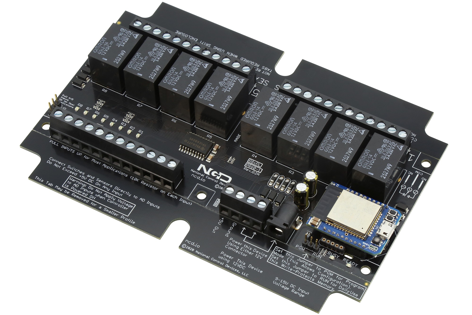
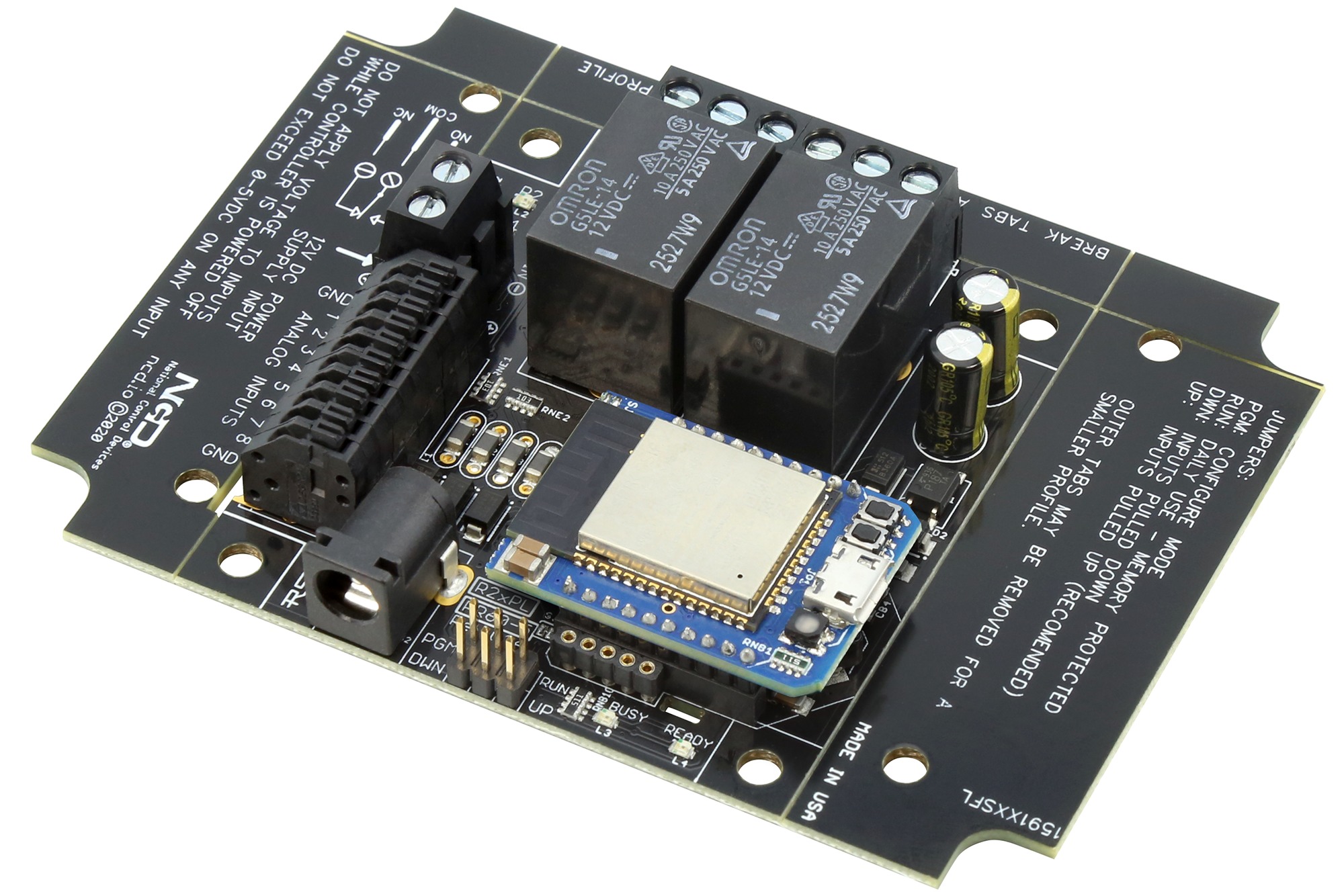
WiFi Relay with 5 or 10 Amp Relays
Highlights
- Industrial Quality WiFi Relay Controller
- Available with 1, 2, 4, or 8 On-Board Relays
- Available with 5 or 10-Amp SPDT Relays
- ProXR Command Set Used by Industry for Many Years
- Supports Windows, Mac, Linux, and Android
- Supports LabVIEW and Visual Studio
- TCP Socket or Virtual Serial Port Communications
- Use NCD Base Station Software to Learn Commands
WiFi Relays from NCD
Our WiFi Relay boards makes it easy for computers of all types to control relays and monitor analog inputs. WiFi Relays allow you turn relays on or off, flash relays continuously, control relays for a duration of time, and control relays in groups using a cross-platform compatible WiFi interface. NCD ProXR Lite series controllers are a widely adopted standard used by industry for many years. Equipped with your choice of 1, 2, 4, or 8 on-board relays, the ProXR Lite series WiFi Relays suit the needs of most of our customers. Integrated Analog to Digital Converters may be used to manually control the relays, or they may be used to read external sensors. Equipped with 8 or 10-Bit resolution, the ADC built into each WiFi Relay adds tremendous flexibility for various application requirements.
WiFi relays support DHCP or a Static IP address with a programmable port number, 2101 is used by default. NCD WiFi communications module will transmit the IP address of the device using periodic UDP broadcasts, which make it easy to locate the device on a network. On-board RGB LED indicates connection status while two on-board buttons may be used to initiate the setup process. In addition to WiFi, the latest generation communications module also supports Bluetooth and USB connectivity.Getting Started with a WiFi Relay
Start by downloading Base Station at https://ncd.io/start and Run the application. A window will appear which listens for all NCD UDP broadcasts. Plug in your WiFi Relay Board and wait for the Network window to populate with the IP address of the WiFi Relay Board. Simply click the IP address of the device and “OK” to establish a connection.
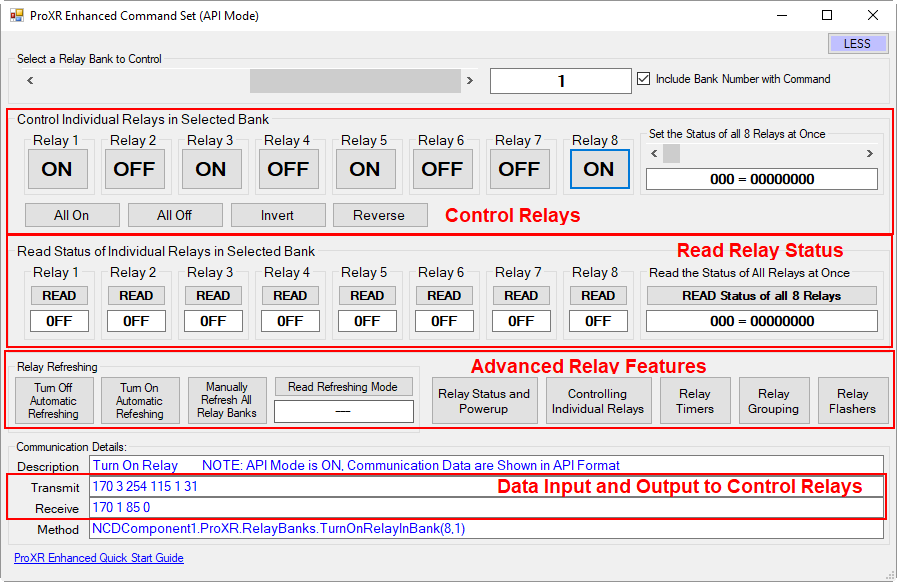
Base Station is a tool designed to teach you all the features built into your controller and provide you with example commands. Base Station was written for Windows using Visual Studio (source code available on the download page linked above). Base Station shows you all the commands you need for controlling relays and monitoring external sensors.New Version Now Shipping
Beginning Late 2020, we’ve made some updates to this product to make it better with increased component count while maintaining the same functionality and footprint. The New Rev G2 Series adds a better power supply circuit to improve noise immunity while providing increased power to the communications socket. We also improved the relay drive circuit to better handle inductive loads. We also changed the color of the circuit board to Black and updated the branding to ncd.io with updated logos.
This is the same product you have been buying for years, but now with improved electronics and while maintaining the same footprint as the original design. Most importantly, this is now a Legacy product, which means it will never go obsolete as long as critical parts are still available to us. Built with our new high-speed pick and place assembly line, we can complete the surface mount assembly process at a rate of several thousand units per day with the potential to scale to any volume you could imagine, so you never need to worry about supply quantities or supply chain problems.
Please note that it was necessary for us to remove the integrated temperature sensor in select versions of this product. This sensor was providing incorrect readings if the relays were active for extended periods of time. We can help you with an off-board sensor if needed.
Updated Features
- Updated Logos and Branding, Changed PCB Color to Black
- Improved Relay Drive Circuit for Greater Noise Immunity
- Improved Power Supply Circuit
- Switcher Regulator for Lower Heat and Higher Power
- Adds Compatibility with NCDD5500 Ethernet Module
- Adds Compatibility with WiFi/Bluetooth Module
- Use MQTT to Talk to this Device via WiFi Module
- Use Integrated Web Page when using our New Ethernet or WiFi Module
- Added Zip Tie Holes to Secure Communications Module
- New Option for Pluggable Connectors on the Analog Inputs
- Ferrite Beads for Improved Noise Separation of Logic and Drive Circuits
- Updated LEDs to Address Supply Chain Limitations
- 100% Identical Firmware with No Changes for Drop In Compatibility
- 99% Identical Shape – Only Slight Changes to Connector Positioning
- Built by our High-Speed Pick and Place Machine for High-Volume Runs
- Legacy Status Product – Will Not Become Obsolete
- Removed Temp. Sensor from Select Versions due to Errant Readings
Base Station Software
Base Station Software was designed to help you learn the ProXR command set. Explore ProXR features using our Graphical User Interface. Watch data bytes flow to and from the board, so you easily understand the command execution process. There is no faster or easier way to learn how to automate than Base Station, as it was designed to work with our complete array of communication modules, including Wireless, Ethernet, USB, RS-232, and many more. You only need a Windows 8 or 10 Computer to Run Base Station. Base Station was written in Visual Studio, and we even provide the source code to help you on your way! Learn More about Base Station Software Here.
AD8 8-Channel 8/10-Bit Analog to Digital Converters
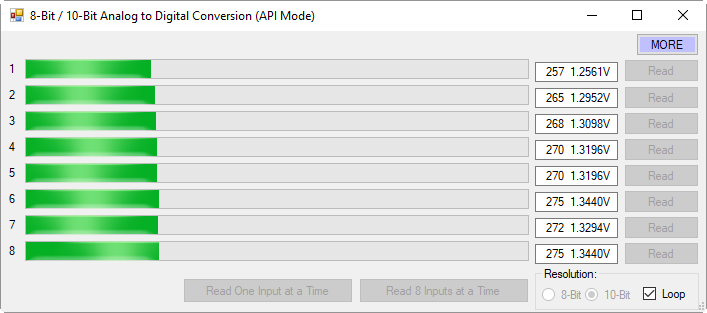
This controller is equipped with 8-Channels of 8/10-Bit Analog to Digital Converters, capable of reading analog voltages from 0 to 5 Volts DC. The ADCs on this controller allow monitoring of external sensors or contact closure input detection. Connect external temperature sensors, light sensors, current sensors, buttons, switches, or anything else that generates a 0-5VDC analog or contact closure output. With 8-bit resolution, analog inputs will convert 0-5 Volt signals into a value from 0 to 255. With 10-bit resolution, values of 0 to 1023 may be measured. Input resolution is software selected. Simply ask the controller for the analog value of each input, and the controller instantly responds.
Relay Activator and Analog Inputs
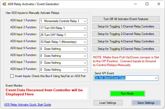
The Relay Activator control panel allows analog inputs to directly control relays. Simply connect the analog inputs to buttons or switches and trigger basic relay on or off functions to take manual control of the on-board relays. The Relay Activator control panel allows you to define 8 functions for each of the 8 inputs. Functions include turning relays on or off, toggling the state of relays, momentarily flash a relay, momentarily toggle the flashing function of a relay, turn all relays on, turn all relays off, and push notification events. When push notification events are configured, the controller generates a packet of data every time the inputs change state.
Learn More about ProXR Series Controllers
Base Station helps you learn how to use ProXR Series relay controllers. In this video, we will cover some of the most commonly used features.
Download Base Station
Download the Latest Version of Base Station and Source Code for Visual Studio.
ProXR Quick Start Guide
Online Manual for ProXR and ProXR Lite Series Controllers
Good to Know!
NCD ProXR Series Controllers have been in production for many years and have amassed a large user base since their initial release in the early 2000s. Due to the large client base, we have no plans to discontinue this line of products. In many cases, we are upgrading these devices to make them compatible with automated assembly processes along with improved driver and power electronics capable of supporting many communication technology changes well into the future. Rest assured, ProXR will continue to be a stable part of our product line for many years to come. ProXR series controllers manufactured with a Black circuit board have been migrated to automated assembly and are considered to be the final iteration of this product. These devices can be manufactured in high volumes in a much shorter period of time.
LabVIEW Relay Control
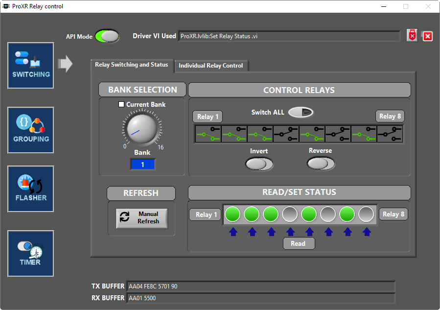
NCD supports integration of NCD relay controllers using LabVIEW. We have included samples and drivers for basic and advanced operation which cover most functions including Relay Timers. We have posted several tutorials on this topic here.
ProXR Lite Communication Options
We take communications seriously, as we believe in modular communications and firmware that properly supports scalability into future interface technologies. ProXR controllers support API communications, which effectively wrap every command with a header, payload, and checksum to ensure reliability. NCD API commands increase processing speed because no serial timeout is required prior to command processing. NCD API commands increase reliability, as only a proper checksum will authenticate a command and allow it to process. When we first implemented API, internet communications via a TCP/IP socket could be realized because the timing problems of internet communications were eliminated. While API is optional, it is strongly advised. Our Base Station software uses API communications, so it’s possible to control a ProXR controller over the internet after configuring port forwarding on your router.
ProXR series controllers are the world’s most adaptable controllers, capable of communicating with a wide variety of communication options. Pick any of your favorite communication technologies: Bluetooth, USB, WiFi, Ethernet, Key Fob, RS-485 or RS-232. ProXR easily adapts to the communication technologies you need most. We are committed to modular communications, so your ProXR series controllers can easily be retrofitted for other applications as your needs change. ProXR controllers are never obsolete, as we are actively releasing new communication technologies that greatly enhance the connectivity of our ProXR series controllers.
Communications Module Included
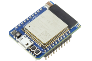
WiFi Bluetooth USB 3 in 1 Module with MQTT Support
Control NCD devices using standard WiFi TCP/IP communications or use the integrated Bluetooth for simple wireless computer to device interface using a wireless virtual COM port. Use the USB port for control over a virtual COM port for easy connectivity. This is a low-cost solution that lets you try different solutions with easy setup using a integrated Web Page User Interface for all Configuration settings. Connect to a MQTT Server over WiFi for remote operation over the internet. Learn More about our WiFi TCP/IP Communications module here.
Bluetooth
Using the Bluetooth SPP Profile, this device will connect to your PC using Bluetooth, Appearing as a Virtual COM Port. Communicate with this Device up to 200 Feet away!
WiFi
Use the Integrated Web Page to Configure Vital Settings and Use TCP Communications to Communicate to the Device using Simple Byte Packets. A integrated Relay Control Web Page is Available for Select NCD Relay Controllers.
USB
Using the USB interface, this Device will Plug into your PC, MAC, or Linux system and install a Virtual COM Port Driver
MQTT and Amazon AWS Connectivity
Connect Directly to MQTT Servers including Amazon AWS and communicate with this device from anywhere in the world. Subscribe to a Topic that contains control bytes to control the connected device. Response bytes from the connected device will be Published to the Cloud.
TCP Communications and UDP
This Communications Module sends UDP Broadcasts to help locate the IP address of the WiFi module on your Network. Once discovered, simply open port 2101 and send and receive bytes of data to control the connected device and read responses over a WiFi network.
Associated Part Numbers
This product may have been previously manufactured using a part number shown below:
Relay Options
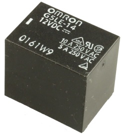
10-Amp SPDT Signal Relay Option
This controller is available with a 10-Amp relay option, allowing control of higher-power loads up to an absolute maximum of 240VAC at 10 Amps. Ideal for general purpose switching applications, this relays is focused on power-switching, and should never be used for low-power signals due to a higher On resistance of up to 150 Ohms when relay contacts are new (contact resistance drops to less than 1 Ohm after break-in period). The 10-Amp relay is of the SPDT variety, which provides Common (C), Normally Open (NO), and Normally Closed (NC) connections. Common is connected to NC when the relay is off. Common disconnects from NC and connects to NO when the relay is activated. All connections are made via screw terminals, capable of accepting up to 12 AWG wire. Review Datasheet
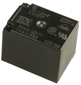
5-Amp SPDT Signal Relay Option
This controller is available with a 5-Amp relay option, allowing control of higher-power loads up to an absolute maximum of 240VAC at 5 Amps. Ideal for general purpose switching applications, this relays is focused on power-switching, and should never be used for low-power signals due to a higher On resistance of up to 150 Ohms when relay contacts are new (contact resistance drops to less than 1 Ohm after break-in period). The 5-Amp relay is of the SPDT variety, which provides Common (C), Normally Open (NO), and Normally Closed (NC) connections. Common is connected to NC when the relay is off. Common disconnects from NC and connects to NO when the relay is activated. All connections are made via screw terminals, capable of accepting up to 12 AWG wire. Review Datasheet
Mechanical Drawing
Wiring Diagrams
Essential
- ProXR Quick Start Guide
- Mechanical Relay Types
- API Codec Quick Start Guide
- Base Station Quick Start Guide
Documentation
Communications
- NexGen WiFi Module User Guide
- (Deprecated – Legacy Hardware) WiFi Communications Module Quick Start Guide
Tutorials
- Unable to Mount Virtual COM Port in Windows 10
- Linux Relay Controller using Netcat for Ethernet and WiFi
- Controlling Inductive Devices: Managing Induction & Electromagnetic Interference
- Introduction to Computer Controlled Relays and Switching
- Relay Logic
LabView Tutorials
- Installing LabVIEW USB RS232 RS485 Relay Controller Instrument Driver
- Labview Relay switching and Status acquisition 1
- LabVIEW Relay Controller Advanced Configuration
- LabVIEW Relay controller Basic Configuration
- LabVIEW Relay switching and Status acquisition 2
- LabVIEW Relay Timer Operation
Official Repository
WiFi Module Setup
The Wi-Fi Communications Module must be configured in order to connect to your network using the Wi-Fi Configuration Kit. The Wi-Fi Configuration Kit consists of a small black board with 3 LEDs. The Configuration Board will be labeled ZIGMO. The module may have to be removed from the board and plugged into the ZIGMO as shown. The ZIGMO will plug into the USB port of your computer for configuration and some USB drivers may need to be installed on your computer. Base Station software is required to configure the Wi-Fi communications module and is available as a free download. This software identifies compatible Wi-Fi routers in your area and assigns the router you have chosen to the Wi-Fi communications module. Network security options may be configured using this software including passwords. You can find the NCD Base Station Software at ncd.io/start.
WiFi Introduction
Introduction to our WiFi Module and technologies. Learn the advantages, disadvantages as well as tips and tricks for using WiFi Relay Controllers available from store.ncd.io. You can find more in depth information on how to use and configure your WiFi Relay Controller at https://ncd.io/wifi-module-quick-start-guide/.
Analog to Digital Converter Introduction
Learn the Basics of Analog to Digital Conversion. Many of our boards have analog to digital inputs directly on the board. These ADC inputs are great for monitoring sensors and controlling relays from software based on these sensor readings. This video will show you how, why, and when to use them.
Introduction to Relay Control
This video will guide you in determining which relay controller you need for your application as well as a general overview of the differences between Relay Options. If you’re new to our products or just need a refresher for a new application this is a great place to start.
Induction Suppression
Learn about Induction and how it comes into play with Relay Controllers. Induction suppression can make your Relay Control applications intermittent and unreliable. This video will show you what causes it, how to avoid it, and how to account for it in your application.
SPDT Relay Controller Specifications
This table covers all NCD SPDT Relay Controllers. All ratings assume 12VDC operation at 70°F (21°C). Please note that most ratings are estimated and may be subject to periodic revision. Some ratings represent stock controller settings without performance enhancement optimizations. The estimated processing time can be impacted by background services and choice of commands. Standby power consumption assume no communications module is installed and no relays are active on the controller. Please add the power consumption of the activated relays and communications module to obtain a better estimation of power consumption.| Specifications of NCD SPDT Relay Controllers | Minimum | Nominal | Maximum | Notes |
|---|---|---|---|---|
| Operational Voltages | 10VDC | 12VDC | 15VDC | |
| Standby Power Consumption | 35mA | 100mA | 200mA | No Active Relays, No Com Module |
| Relay Power Consumption | 28mA | 35mA | 60mA | Consumption of Each Activated Relay |
| Operational Temperature Range | -40°F (-40°C) | 70°F (21°C) | 185°F (85°C) | Theoretical Component Limits Shown |
| Storage Temperature Range | -67°F (-55°C) | 70°F (21°C) | 185°F (85°C) | Theoretical Component Limits Shown |
| Operational Ambient Air Humidity | 0% | 50% | 70% | Non-Condensing Humidity Values Shown |
| Relay Activation Time | 4ms | 5ms | 10ms | Needs Further Validation |
| Relay Deactivation Time | 5mS | 10mS | 15mS | Needs Further Validation |
Communication Module Specifications
This table covers all NCD Communication Modules. While NCD communication modules operate at 3.3VDC, the ratings below highlight the effect they will have on the master controller operating at 12VDC at 70°F (21°C). Maximum ratings should be used for power budget planning purposes and may reflect short term absolute maximum peak current consumption. Some ratings are estimated and subject to periodic revision.| Specifications of NCD Communication Modules | Minimum | Nominal | Maximum | Notes |
|---|---|---|---|---|
| Operational Temperature Range | -40°F (-40°C) | 70°F (21°C) | 185°F (85°C) | Theoretical Component Limits Shown |
| Storage Temperature Range | -67°F (-55°C) | 70°F (21°C) | 185°F (85°C) | Theoretical Component Limits Shown |
| Operational Ambient Air Humidity | 0% | 50% | 70% | Non-Condensing Humidity Values Shown |
| USB Communications Module Power Consumption | NA | NA | NA | USB Modules are Powered by the USB Port Do Not Consume Device Current |
| RS-232 Communications Module Power Consumption | 10mA | 20mA | ||
| RS-485 Communications Module Power Consumption | 20mA | 35mA | ||
| Ethernet Communications Module Power Consumption | 58mA | 82mA | 100mA | |
| WiFi Bluetooth USB Communications Module Power Consumption | 37mA | 50mA | 100mA | Up to 300 Foot Indoor Wireless Range, Unobstructed. Up to 50 Foot Range Through Walls. |
| 900MHz Wireless Communications Module Power Consumption | 13mA | 30mA | 50mA | Up to 1,000 Foot Indoor Wireless Range, up to 2 Mile Outdoor Wireless Range using Included Antennas. Up to 28 Miles Outdoor Wireless Range using High-Gain Antennas. |
| 868MHz Wireless Communications Module Power Consumption | 17mA | 30mA | 50mA | |
| 2.4GHz Wireless Communications Module Power Consumption | 8mA | 20mA | 30mA | |
| KFX Wireless Key Fob Communications Module Power Consumption | 11mA | 15mA | 25mA | Up to 200 Feet Outdoor Wireless Range using 1, 2, 3, 4, or 5 Button Key Fobs. Up to 700 Feet Outdoor Wireless Range using 8-Button Remotes. |
AD8 Analog Input Usage Notice
Analog Inputs should not have a voltage present when powered down. Use a 220 Ohm current limiting resistor on each input to prevent damage to the controller if voltage will be present on the analog input when this controller is powered down. Do not exceed 0 to 5VDC on any analog input or the on-board CPU will be damaged. Most analog inputs include a 10K Pull Up/Down resistor to help keep the inputs quiet when not in use. This 10K resistor may slightly bias the readings of some sensors.


