Reactor Sensor Controlled 4-Channel High-Power Relay Board + 8-Channel 8-Bit ADC
Highlights
- 4 On-Board Sensor Controlled Mechanical Relays
- Ideal for High-Power Switching Applications
- Choose Between 20-Amp SPDT or 30-Amp SPST Relays
- Stand-Alone Operation, Only Requires PC for Initial Setup
- 8 Analog Inputs Trigger Relays Based on User Configuration
- 8 Background Timers Offer Timed Relay Switching Functions
- 4 Rotation Counters Trigger Relays Based on Counting Values
- Use a Computer to Take Control of the Reactor Logic
- CPU Status LEDs Show Command Processing Activity
- Optional Key Fob for Long-Range Remote Operation
- Modular Communications Interface for Use with:
- USB, Bluetooth, WiFi, RS-232, Key Fob, or Ethernet
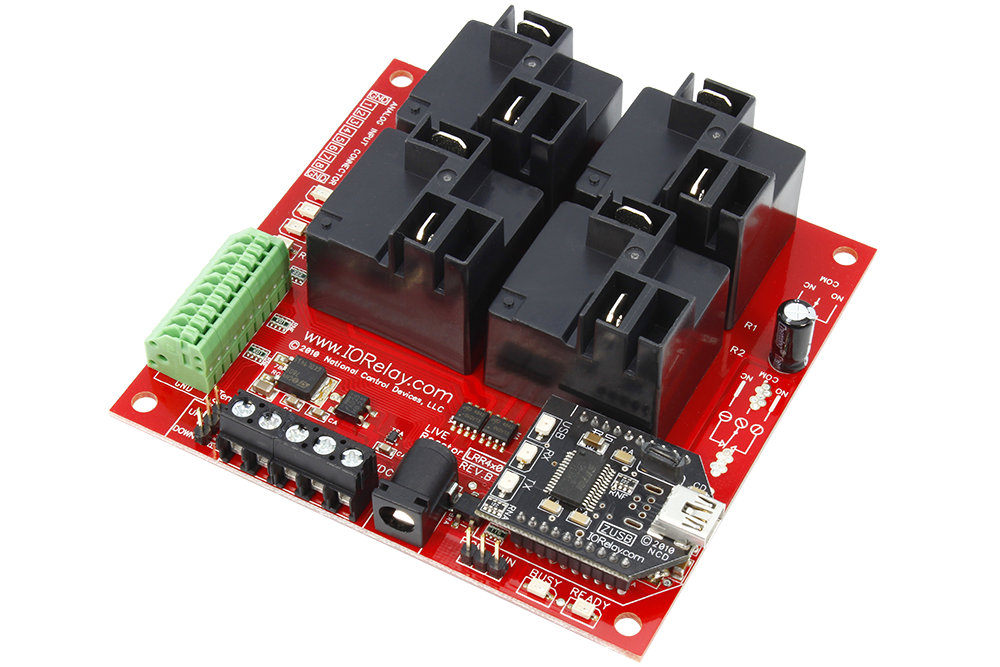
4-Channel Sensor Controlled High-Power Relays
This 4-Channel High-Power Reactor Relay Controller makes it easy for sensors to directly control external lights, motors, and other high-power electrical devices based on environmental actions or conditions. Use external sensors to activate relays for a pre-set time period. A single external sensor is capable of controlling multiple relays or relay sequences based on your configuration. Use a computer to configure the Reactor. Once configured, Reactor works stand-alone, or in combination with a PC, depending on your application requirements. Reactor is compatible with many popular communication technologies, providing a upgrade path should your needs change in the future. Mechanical Relays are an ideal for choice for most users because of their long-life and low cost. Inductive loads such as Motors, Valves, Pumps, Solenoids, and Large Transformers (including Fluorescent Lighting) will require external induction suppression capacitors to reduce interference to acceptable levels.
Reactor Relay Control
Sensor Controlled Relays Expand Automation WITHOUT Programming!
Intelligent Switching without a Computer is the foundation of the Reactor Series relay controllers. Reactor connects the real world to the electronics world, making it easy to configure and control real-world devices for simple automation tasks.
Reactor Automation Applications
Reactor can activate a light when it gets dark outside. Reactor can close a door that has been left open too long. Reactor can activate a heater to help maintain temperature. Reactor can turn on a light for 10 minutes if motion is detected. Reactor can water your crops when the soil moisture becomes too dry.
Configure Once, Automate Forever!
Reactor controllers are configured using our Free Base Station Software. Our simple GUI interface makes it easy to configure simple automation tasks with a point and click interface. Set parameters to activate relays within user-defined limits. Trigger timers, counters, and relay sequences with just a few clicks.
Once configured, the Reactor CPU will constantly monitoring external sensors using 8 analog inputs. When sensors reach pre-set limits, relays will be activated according to your configuration. Reactor is commonly used as a thermostat, motion activated light controller with a programmable timer, an automatic garage door closer, and much more.
Who’s Qualified to Use the Reactor Series?
Some computer skills are required. The Reactor series controllers do not require programming, simply configure the device with our Free Base Station Software. While programming is not required and simple functions can be done rather easily with basic computer skills, complex events may be possible with experimentation.
Sensors
The Reactor series controllers include 8 analog inputs, capable of reading switches, resistance changes, or voltages from 0 to 5VDC. Higher or lower voltages will damage the Reactor controller, so care must be taken not to exceed the voltage limits on the Reactor inputs. We offer many sensors to help get you started, including temperature sensors, light sensors, current sensor, and magnetic proximity sensors. You can connect your own sensors to the Reactor if we don’t offer what you are looking for. The Reactor configuration will control how the sensor affects the relay.
Complex Automation through Experimentation
Don’t be afraid to experiment with Reactor. Some complex automation can be achieved by experimenting with Reactor settings. Of course Reactor is capable of triggering relays, but did you know that Reactor can also trigger events? Relays can be associated with events, allowing you to play with all kinds of complex timing and counting settings. Events greatly expand the pallet of functionality available to Reactor.
Computer Controlled Relays
Software developers who need remote access to a Reactor controller will find themselves at home. The Reactor supports a very powerful computer-based command set, so it is possible for a computer to operate the relays and read sensor inputs. The computer can over-ride the Reactor decision logic, trigger events, and return control of the relays back to the Reactor Logic. Configuration settings are stored in files that can be loaded into other Reactor controllers.
Removable Communications Module
Once configured, Reactor controllers operate on their own, without a computer. Reactor will never lose its settings. In fact, the communication module can be removed from the Reactor controller and used to configure another Reactor controller. This helps keep costs down. If you choose to leave the communication module installed on the Reactor, your computer can monitor inputs and control relays.
Communications Module Options
Reactor supports many communications technologies, including USB, RS-232, Bluetooth, Ethernet, and Industrial Wireless. We recommend the USB option, as Reactor focuses on automation, and is frequently used without any communications module once configured. Nonetheless, please feel free to choose the technology that best suits your needs as our Base Station software supports them all. Additional accessories will be required when selecting the KFX Key Fob option, as the Key Fob module must also be configured and does not include any remote controls.
Associated Part Numbers
This product may have been previously manufactured using a part number shown below:
Relay Options

20-Amp SPDT High Power Relay Option
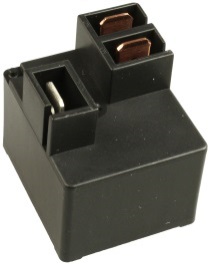
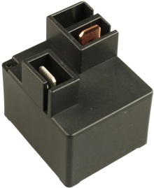
This controller is available with a 20-Amp relay option, allowing control of high-power loads up to an absolute maximum of 240VAC at 20 Amps. Ideal for high-power switching applications, this relay should never be used for low-power signals. The 20-Amp relay is of the SPDT variety, which provides Common (C), Normally Open (NO), and Normally Closed (NC) connections. Common is connected to NC when the relay is off. Common disconnects from NC and connects to NO when the relay is activated. This relay is Rated at 20-Amps between NO and C. Do not exceed 10-Amps between C and NC connections. This relay uses .250″ Quick Connect terminals (optional accessory) to connect to the top side of the relay. The relay is molded with COM, NC, and NO markings into the plastic. Review Datasheet

30-Amp SPST High Power Relay Option
This controller is available with a 30-Amp relay option, allowing control of high-power loads up to an absolute maximum of 240VAC at 30 Amps. Ideal for high-power switching applications, this relay should never be used for low-power signals. The 30-Amp relay is of the SPST variety, which provides Common (C) and Normally Open (NO) connections. Common has no connection when the relay is off. Common connects to NO when the relay is activated. This relay uses .250″ Quick Connect terminals (optional accessory) to connect to the top side of the relay. The relay is molded with COM, NO markings into the plastic. Review Datasheet
Mechanical Drawing
Wiring Diagrams
Essential
Communications
Tutorials
- Using Comm Operator to Control USB Relays
- Choosing the Right USB Relay Controller
- Controlling Inductive Devices: Managing Induction & Electromagnetic Interference
- Introduction to Computer Controlled Relays and Switching
- Relay Logic
Documentation Downloads
Download NCD Base Station
USB Intro
We explain the advantages and disadvantages to USB communications and how it effects our Relay Controllers and your application. Some of the information is outdated as we’ve moved away from controlanything.com. Most modern operating systems come with the FTDI driver installed so you should just need Base Station
USB FTDI Communication Module Compatible with the Digi XBee ® Controlling Relay
FT232RL USB Interface Adapter Similar to the Digi XBee ® footprint shown controlling a 16-Channel Relay Controller Board Available from https://store.ncd.io/product/usb-communications-module-ft232rl-zusb/ Drivers Available from FTDI: http://www.ftdichip.com/FTDrivers.htm Base Station Software: ncd.io/start Digi.com offers a wide variety of XBee Interface modules for industrial wireless applications. Digi XBee® devices are compatible with NCD products.
USB Setup
Learn how to set up you own ZUSB Module to work with your NCD Relay Controller. For complete instructions and details on how to use an NCD ZUSB Module see our article at https://ncd.io/zusb-usb-communications-module-quick-start-guide/ Portions of this video may be outdated as we have moved from controlanything.com since this video was created.
Finding the Com Port
Learn how to find the COM Port on your windows based computer. You can also use Base Station to find the COM Port of your Relay Controller. Base Station can be downloaded at ncd.io/start.
Wired Communications
Get the rundown on the pros and cons of all the Wired Communication Interfaces we offer. If you want to know which wired technology will best suit your needs this video will get you the information you need in just a few minutes. Whether you need the power of ethernet or the simplicity of RS-232 we have something to fit your application.
Introduction to Relay Control
This video will guide you in determining which relay controller you need for your application as well as a general overview of the differences between Relay Options. If you’re new to our products or just need a refresher for a new application this is a great place to start.
Induction Suppression
Learn about Induction and how it comes into play with Relay Controllers. Induction suppression can make your Relay Control applications intermittent and unreliable. This video will show you what causes it, how to avoid it, and how to account for it in your application.
Hiph-Power Relay Controller Specifications
This table covers all NCD High-Power Relay Controllers. All ratings assume 12VDC operation at 70°F (21°C). Please note that most ratings are estimated and may be subject to periodic revision. Some ratings represent stock controller settings without performance enhancement optimizations. The estimated processing time can be impacted by background services and choice of commands. Standby power consumption assume no communications module is installed and no relays are active on the controller. Please add the power consumption of the activated relays and communications module to obtain a better estimation of power consumption.| Specifications of NCD SPDT Relay Controllers | Minimum | Nominal | Maximum | Notes |
|---|---|---|---|---|
| Operational Voltages | 10VDC | 12VDC | 15VDC | |
| Standby Power Consumption | 35mA | 100mA | 200mA | No Active Relays, No Com Module |
| Relay Power Consumption | 28mA | 35mA | 60mA | Consumption of Each Activated Relay |
| Operational Temperature Range | -40°F (-40°C) | 70°F (21°C) | 185°F (85°C) | Theoretical Component Limits Shown |
| Storage Temperature Range | -67°F (-55°C) | 70°F (21°C) | 185°F (85°C) | Theoretical Component Limits Shown |
| Operational Ambient Air Humidity | 0% | 50% | 70% | Non-Condensing Humidity Values Shown |
| Relay Activation Time | 15ms | Component Rating Shown | ||
| Relay Deactivation Time | 10mS | Component Rating Shown | ||
| Operational Life Mechanical | 10,000,000 | Component Operation Rating | ||
| Operational Life Electrical | 100,000 | Component Rating at Maximum Load |
Communication Module Specifications
This table covers all NCD Communication Modules. While NCD communication modules operate at 3.3VDC, the ratings below highlight the effect they will have on the master controller operating at 12VDC at 70°F (21°C). Maximum ratings should be used for power budget planning purposes and may reflect short term absolute maximum peak current consumption. Some ratings are estimated and subject to periodic revision.| Specifications of NCD Communication Modules | Minimum | Nominal | Maximum | Notes |
|---|---|---|---|---|
| Operational Temperature Range | -40°F (-40°C) | 70°F (21°C) | 185°F (85°C) | Theoretical Component Limits Shown |
| Storage Temperature Range | -67°F (-55°C) | 70°F (21°C) | 185°F (85°C) | Theoretical Component Limits Shown |
| Operational Ambient Air Humidity | 0% | 50% | 70% | Non-Condensing Humidity Values Shown |
| USB Communications Module Power Consumption | NA | NA | NA | USB Modules are Powered by the USB Port Do Not Consume Device Current |
| RS-232 Communications Module Power Consumption | 10mA | 20mA | ||
| RS-485 Communications Module Power Consumption | 20mA | 35mA | ||
| Ethernet Communications Module Power Consumption | 58mA | 82mA | 100mA | |
| WiFi Bluetooth USB Communications Module Power Consumption | 37mA | 50mA | 100mA | Up to 300 Foot Indoor Wireless Range, Unobstructed. Up to 50 Foot Range Through Walls. |
| 900MHz Wireless Communications Module Power Consumption | 13mA | 30mA | 50mA | Up to 1,000 Foot Indoor Wireless Range, up to 2 Mile Outdoor Wireless Range using Included Antennas. Up to 28 Miles Outdoor Wireless Range using High-Gain Antennas. |
| 868MHz Wireless Communications Module Power Consumption | 17mA | 30mA | 50mA | |
| 2.4GHz Wireless Communications Module Power Consumption | 8mA | 20mA | 30mA | |
| KFX Wireless Key Fob Communications Module Power Consumption | 11mA | 15mA | 25mA | Up to 200 Feet Outdoor Wireless Range using 1, 2, 3, 4, or 5 Button Key Fobs. Up to 700 Feet Outdoor Wireless Range using 8-Button Remotes. |
Analog Inputs: 0 to 5 Volt Only
Analog inputs can accept voltages from 0 to 5VDC ONLY. Higher voltages and negative voltages will damage the Reactor controller. Users must NEVER apply a voltage to an analog input on the Reactor controller when powered down.
Compatible Sensors
If you would like to see all the sensors compatible with Reactor controllers, please click here (link opens in a new window).
ZUSB Communication Module Recommended
All customers are STRONGLY ADVISED to purchase at least ONE USB Communication Module (choose ZUSB during the order process). This communication module may be used to recover a controller or to reconfigure a controller should there be an accidental loss of communications. NCD Tech support may be unable to assist customers who do not have a USB Communications Module available for troubleshooting purposes.
Ethernet TCP/IP Compatibility Notes
This device periodically sends UDP Packets on port 13,000, which help identify the IP address of this device on your network.
RS-232 Serial Compatibility Notes
The NCD RS-232 Serial communications module is compatible with standard RS-232 signals (+/-10VDC), which are not directly compatible with UART signals from a microprocessor. If you are working with Arduino, Microchip PIC, or other common microcontroller, a communications module is not required. Microcontrollers will directly talk to the on-board processor of all NCD controllers.


