Direct Wired Contact Closure Transmitter Receiver 8-Channel High-Power Relays 2-Way
Please note that images above may contain product not included with purchase.
Highlights
- 8-Channel High-Power Relays and Inputs on Each Controller
- Sold in Pairs with up to 1000′ Range 3-Wire Connection
- Each Device Controls the Other Device
- Local Inputs Control Remote Relays
- Remote Inputs Control Local Relays
- 2-Way Communication with Verification
- No Configuration, Computers, or Programming
- Beacon Mode for Range Testing
- Smart Mode for Fast, Low Power Operation
- Relay and Communication LED Status Lights
- Auto Shut-Off when Communications is Lost
Wired Contact Closure 2-Way Transmitter Receiver Pair
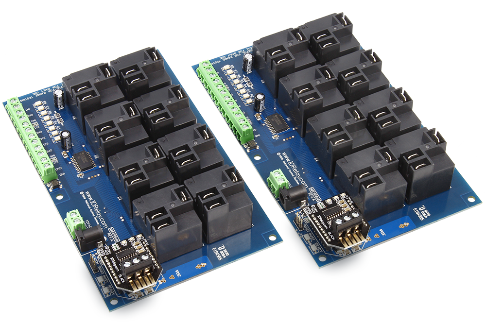
Our MirX 8-Channel High-Power Relay Controllers are manufactured in pairs, designed to work together when powered up using 3-wire communications. The contact closure inputs on controller A control the relays on controller B. Similarly, the contact closure inputs on controller B control the relays on controller A. MirX controllers communicate to each other using just 3 wires over distances up to 1,000 feet. Use just about any type of network wire, including Cat3, Cat5, Cat6, or whatever else you may have for best communication distance. MirX controllers use screw terminals to connect 3 communication wires between controllers.
This pair of MirX controllers is equipped with your choice of 20-Amp SPDT or 30-Amp SPST relays, ideal for use in most high-power switching applications. Ideal for lights, motors, gate openers, pump controllers, valve controllers, and much more. On-board Relay status LEDs and busy/ready LEDs let you know when these controllers are talking to each other. When communications is lost, on-board relays will automatically deactivate within 30 seconds (user selectable option).
Wireless MirX Remote Contact Closure Transmitter and Receiver Controllers
MirX Controllers Mirror Consist of two Identical controllers. These controllers are equipped with contact closure inputs and relays. The contact closure inputs on controller one are replicated on controller two. Similarly, the contact closure inputs on controller two are replicated on controller one. Mirror controllers are paired and ready to go to work immediately. No Computers, No Configuration – Works Right Out of the Box. MirX controllers stay connected to each other using 3 communication wires, preferably high-quality network cable such as CAT3 or better. Other types of cable will work, but may affect range.
Permanently Married
MirX is Always Trying to Talk to it’s Mate!
MirX controllers are always talking to each other. They stay in relentless communications for optimal reliability. Should they lose communication with each other, they will keep calling out for each other until they find their mate.
Syncing Up
Every MirX controller is equipped with contact closure inputs and relay outputs. The inputs on one controller activate the relays on the remote device using wireless communications. The “X” in MirX refers to the crossover. Since both devices are equipped with contact closure inputs and relays, each device targets and controls the remote device. Every MirX controller is equipped with a Busy/Ready LED. If the Busy LED flashes, this indicates the remote device has successfully received and accepted your contact closure status. If the Busy LED does not flash, the remote device is out of range.

Beacon Mode
Beacon Mode communicates with a Remote MirX controller many times per second, refreshing Relay Status information every time a valid data stream is received by the remote device. Relays are only refreshed when a valid data packet is received. If data is lost, the Ready LED will stay on and Relays will stay in their current state. If the remote MirX controller is properly connected, the Busy LED will flash periodically, indicating valid communications between devices. Beacon Mode is slower than Smart Mode and is used primarily for initial testing of two devices.
Smart Mode
Once you have determined an installation location for both MirX controllers, move the Beacon/Smart jumper to the Smart position. Smart Mode communicates to the remote device any time a change is detected on the local device. Otherwise, the controller periodically checks to make sure the remote device is connected. Smart Mode is significantly faster than Beacon Mode. Smart Mode is the preferred mode for daily use in most applications. Note that each MirX controller can be set to a different mode and jumper changes take effect immediately. Again, the Busy LED will indicate the remote device is properly communicating. Smart Mode will also verify the relays on the remote device are properly set. If they are not, Smart Mode will attempt communications until the remote device responds. If communications is lost between the MirX controllers, all relays will automatically shut off within 30 seconds. If this is not desirable, Beacon Mode should be used.
Beacon Mode vs. Smart Mode
Perhaps the most notable difference between Beacon and Smart Mode is how relays respond if communication is lost. In Beacon Mode, the relays will stay in their current state and will not change unless a new data packet is received. In Smart Mode, relays will turn off automatically in 10 to 30 seconds if communications is lost between MirX controllers.
Wired Range
The distance between MirX controllers will affect reliable operation. With the direct wired version of MirX, you should expect to get a range of 1,000 feet using a 3-wire cable. The cable can be any common network cable such as Cat3, 4, 5, or 6, or standard telephone or similar cable. The wires attach to a 3-wire terminal block directly to the MirX controllers.
Applications
MirX controllers are typically used by our large industrial clients for a wide range of remote control switching applications. Typical installations include remote gate operation, remote light control, remote pump control, as well as various temperature override applications. Since MirX includes relays on each side, local relays are typically used for verification purposes, such as limit switches or remote door switches, indicating the remote device has completed its control function. MirX controllers are typically used instead of expensive trenching and drilling applications where running wire can be destructive and sometimes cost prohibitive. MirX is commonly used in signage applications that may require a warning light as a supplement to a standard traffic light. MirX is also used by our customers to provide remote operation of lights, doors, gates, motors, pumps, and valves.
Other Mirror Family Controllers
- MirX consists of relays and contact closure inputs on each controller (local and remote). Inputs in the home location control the relays in the remote location. Inputs in the remote location control the relays in the home location.
- MirC is the same as MirX except MirC consists of contact closures on one controller and relays on the remote controller.
- MirW consists of several contact closure input boards and a single relay controller. All remote contact closure inputs are used to control local relays.
MirX Variations
NCD manufactures several variations of MirX as well as other Mirror series devices. Here are some variations you may wish to consider:
- MirX Wireless for remote control applications with Wireless Encryption
- MirX Wired for hard-wired communication applications
- MirX Network for local area Ethernet communications in a Local Area
Relay Options
MirX offers several relay options, depending on your application. We stock solid-state, high-power, and general purpose relays in our MirX line of products. However, we can customize our MirX controllers to your exact needs. Please contact us if you need any custom designed MirX controllers, including different relay types or firmware modifications. This particular controller has the following relay options available:
Associated Part Numbers
This product may have been previously manufactured using a part number shown below:
Relay Options

20-Amp SPDT High Power Relay Option
This controller is available with a 20-Amp relay option, allowing control of high-power loads up to an absolute maximum of 240VAC at 20 Amps. Ideal for high-power switching applications, this relay should never be used for low-power signals. The 20-Amp relay is of the SPDT variety, which provides Common (C), Normally Open (NO), and Normally Closed (NC) connections. Common is connected to NC when the relay is off. Common disconnects from NC and connects to NO when the relay is activated. This relay is Rated at 20-Amps between NO and C. Do not exceed 10-Amps between C and NC connections. This relay uses .250″ Quick Connect terminals (optional accessory) to connect to the top side of the relay. The relay is molded with COM, NC, and NO markings into the plastic. Review Datasheet

30-Amp SPST High Power Relay Option
This controller is available with a 30-Amp relay option, allowing control of high-power loads up to an absolute maximum of 240VAC at 30 Amps. Ideal for high-power switching applications, this relay should never be used for low-power signals. The 30-Amp relay is of the SPST variety, which provides Common (C) and Normally Open (NO) connections. Common has no connection when the relay is off. Common connects to NO when the relay is activated. This relay uses .250″ Quick Connect terminals (optional accessory) to connect to the top side of the relay. The relay is molded with COM, NO markings into the plastic. Review Datasheet
Mechanical Drawing
Wiring Diagrams

Introduction to Relay Control
This video will guide you in determining which relay controller you need for your application as well as a general overview of the differences between Relay Options. If you’re new to our products or just need a refresher for a new application this is a great place to start.
MirX
Learn how MirX Relay Controllers work and how to get the most out of them. MirX is a powerful two way relay control technology using simple contact closures to control remote relays. A contact closure in one location trigger the corresponding relay in another location on a married pair. No wires, no software, it just works. This contact closure can be a simple switch, or any sensor that outputs a contact closure such as some current sensors and most proximity sensors.
Induction Suppression
Learn about Induction and how it comes into play with Relay Controllers. Induction suppression can make your Relay Control applications intermittent and unreliable. This video will show you what causes it, how to avoid it, and how to account for it in your application.
Hiph-Power Relay Controller Specifications
This table covers all NCD High-Power Relay Controllers. All ratings assume 12VDC operation at 70°F (21°C). Please note that most ratings are estimated and may be subject to periodic revision. Some ratings represent stock controller settings without performance enhancement optimizations. The estimated processing time can be impacted by background services and choice of commands. Standby power consumption assume no communications module is installed and no relays are active on the controller. Please add the power consumption of the activated relays and communications module to obtain a better estimation of power consumption.| Specifications of NCD SPDT Relay Controllers | Minimum | Nominal | Maximum | Notes |
|---|---|---|---|---|
| Operational Voltages | 10VDC | 12VDC | 15VDC | |
| Standby Power Consumption | 35mA | 100mA | 200mA | No Active Relays, No Com Module |
| Relay Power Consumption | 28mA | 35mA | 60mA | Consumption of Each Activated Relay |
| Operational Temperature Range | -40°F (-40°C) | 70°F (21°C) | 185°F (85°C) | Theoretical Component Limits Shown |
| Storage Temperature Range | -67°F (-55°C) | 70°F (21°C) | 185°F (85°C) | Theoretical Component Limits Shown |
| Operational Ambient Air Humidity | 0% | 50% | 70% | Non-Condensing Humidity Values Shown |
| Relay Activation Time | 15ms | Component Rating Shown | ||
| Relay Deactivation Time | 10mS | Component Rating Shown | ||
| Operational Life Mechanical | 10,000,000 | Component Operation Rating | ||
| Operational Life Electrical | 100,000 | Component Rating at Maximum Load |
Communication Module Specifications
This table covers all NCD Communication Modules. While NCD communication modules operate at 3.3VDC, the ratings below highlight the effect they will have on the master controller operating at 12VDC at 70°F (21°C). Maximum ratings should be used for power budget planning purposes and may reflect short term absolute maximum peak current consumption. Some ratings are estimated and subject to periodic revision.| Specifications of NCD Communication Modules | Minimum | Nominal | Maximum | Notes |
|---|---|---|---|---|
| Operational Temperature Range | -40°F (-40°C) | 70°F (21°C) | 185°F (85°C) | Theoretical Component Limits Shown |
| Storage Temperature Range | -67°F (-55°C) | 70°F (21°C) | 185°F (85°C) | Theoretical Component Limits Shown |
| Operational Ambient Air Humidity | 0% | 50% | 70% | Non-Condensing Humidity Values Shown |
| USB Communications Module Power Consumption | NA | NA | NA | USB Modules are Powered by the USB Port Do Not Consume Device Current |
| RS-232 Communications Module Power Consumption | 10mA | 20mA | ||
| RS-485 Communications Module Power Consumption | 20mA | 35mA | ||
| Ethernet Communications Module Power Consumption | 58mA | 82mA | 100mA | |
| WiFi Bluetooth USB Communications Module Power Consumption | 37mA | 50mA | 100mA | Up to 300 Foot Indoor Wireless Range, Unobstructed. Up to 50 Foot Range Through Walls. |
| 900MHz Wireless Communications Module Power Consumption | 13mA | 30mA | 50mA | Up to 1,000 Foot Indoor Wireless Range, up to 2 Mile Outdoor Wireless Range using Included Antennas. Up to 28 Miles Outdoor Wireless Range using High-Gain Antennas. |
| 868MHz Wireless Communications Module Power Consumption | 17mA | 30mA | 50mA | |
| 2.4GHz Wireless Communications Module Power Consumption | 8mA | 20mA | 30mA | |
| KFX Wireless Key Fob Communications Module Power Consumption | 11mA | 15mA | 25mA | Up to 200 Feet Outdoor Wireless Range using 1, 2, 3, 4, or 5 Button Key Fobs. Up to 700 Feet Outdoor Wireless Range using 8-Button Remotes. |
Notes
MirX devices are only sold as a permanently married pair, pricing shown on our web site indicates pricing for the pair of controllers. Contact Closure Inputs may only be connected to switches, buttons, or sensors with Contact Closure capability. Not suitable for use in voltage detection applications. MirX devices use RS-232 two-say serial communications at 1200 Baud. Data is transacted using two-way communications to ensure the remote device is properly functioning. The Busy LED is always used to indicate a properly functioning remote device. If you do not see the Busy LED flash, then the MirX controller is unable to communicate to the remote device. A flashing busy LED is your verification that all communications are functioning properly between MirX controllers.
Customers who require inductive switching (such as motors, lights, pumps, solenoids, and Transformers) should visit the Induction Suppression portion of our web site.
No Voltage Input
Please Note: Users must NEVER apply any voltage to an input on the MirX controller, these inputs are for Contact Closure connections only.
No Voltage Output
Please Note: Relays provide a contact closure output. They do not provide a voltage output. On-Board relays will switch a voltage that is provided externally by the user.